
Building Statistics
General Building Data
General Building Data
General Building Data
Cost Data
Part 1
Building Name
Location
Occupant
Occupancy Type
Size
Number of Stories
A1
A2
A3
Project Delivery Method
Start
Finish
Mid Atlantic Mixed-Use Building
Middle Atlantic, United States
Confidential
Mixed-Use
1,700,000 Sqft
54
32
25
13
Design-Build
Winter 2016
Fall 2019
Total Construction Cost
Structural
Mechanical/Plumbing
Electrical
$310 Million
$65 Million
$40 Million
$24 Million
General Building Data
Owner
General Contractor
Architect
Structural Engineer
Mechanical Engineer
Electrical Engineer
Civil Engineer
Landscape Engineer
Confidential
Clark Construction
Confidential
Confidential
Confidential
Confidential
Confidential
Confidential
Building Architecture
The architects of the Mid Atlantic Mixed-Use Building were inspired to create a modern mixed-use space that was unlike any other building in the area at the time. The building is unique in its design with a nine-story podium that sits on top of two below grade garage levels, and contains ground floor retail, nine floors of garage cutting through the center, and apartment units running along the exterior. After the ninth floor the three towers separate into their own spaces. These towers, designated A1, A2, and A3 are 32, 25, and 13 floors respectively. Tower A1 and A3 contain apartment units, and tower A2 contains luxury condominiums.

Figure 1: A1, A2, A3 Towers
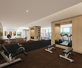
Figure 2: Fitness Center
Codes
The following list contains building codes that were used for the project.
-
2012 Virginia Uniform Statewide Building Code (USBC)
-
2012 Virginia Statewide Fire Prevention Code (SFPC)
-
2011 NFPA 70, National Electrical Code with location specific amendments in Chapter 27 of the USBC
-
2012 International mechanical Code (IMC) with location specific amendments in Chapter 28 of the USBC
-
2012 International Plumbing Code (IPC) with location specific amendments in Chapter 29 of the USBC
-
2010 NFPA 10, Standard for Portable Fire Extinguishers
-
2010 NFPA 13, Standard for the Installation of Sprinkler Systems
-
2010 NFPA 14, Standard for the Installation of Standpipe and Hose Systems
-
2010 NFPA 20, Standard for the Installation of Stationary Pumps for Fire Protection
-
2010 NFPA 72, National Fire Alarm Code
-
2010 NFPA 110, Standard for Emergency and Standby Power Systems
-
2009 NFPA 720, Standard for the Installation of Carbon Monoxide (CO) Detection and Warning Equipment
-
2010 AME A17.1, Safety Code for Elevators and Escalators with 2008 and 2009 addenda
-
Fire Prevention Code of County – Chapter 62 Fire Protection (FFPC). January 2012
-
2012 County Code Reference Package (CRP)
-
2011 County Public Facilities Manual (PFM)

Figure 3: Communal Lounge Area
Zoning
The building is subject to the location specific county’s conceptual development plan (CDP) and final development plan (FDP) reviews. The project zoning is also in compliance with national and local codes in the fire protection plan, and the location specific county’s public facilities manual and 2012 pool code. Figure 4 below shows the limits of the final development plan reviews.

Figure 4: Final Development Plan Reviews
Historical Requirements
Not Applicable
Building Enclosure
The Mid Atlantic Mixed-Use Building uses three primary forms of building exterior. Figure 5 below is a good viewpoint that shows how the three towers and podiums differ in appearance. Towers A1 (left) and A2 (back right) are covered with concrete precast, while the podium and tower A3 are covered with brick veneer.
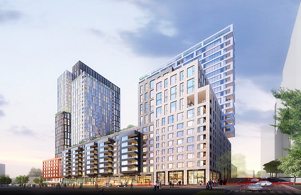
Figure 5: Mid Atlantic Mixed-Use Building
Tower A1
From Interior to Exterior:
½” GWB
3-5/8” Stud to Deck
Air Gap
4” Normal-Rise Spray Foam Insulation with Plastic Stop Angles
Laminated Glass
1 of 3 Precast Panels: Light Gray Concrete Panel, Medium Gray Concrete Panel, Medium Gray Custom Texture Concrete Panel
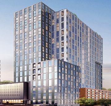

Figure 6: Tower A1 Exterior Section
Figure 7 shows tower A1 exterior construction. The different types of precast that were mentioned above allowed the architect to come up with a customized pattern that increased the tower’s aesthetics.
Figure 7: Tower A1 Rendering
Tower A2
From Interior to Exterior:
½” GWB
3-5/8” Stud to Deck
6” Insulation
Laminated Glass
1 of 2 Precast Panels:
White, Smooth Concrete Panel
Medium Gray, Smooth Concrete Panel


Figure 8: Tower A2 Exterior Section
As mentioned above, Tower A2 uses two types of concrete precast panel: white, smooth and medium gray, smooth. To achieve a unique architectural design the architects on the project created a pattern using the two different types of precast. Figure 9, on the left, shows a balcony view of Tower A2 with the white, smooth concrete precast.
Figure 9: Tower A2 Exterior Rendering
Tower A3 & Podium
From Interior to Exterior:
½” GWB
Variable Permeance Vapor Barrier
6” Insulation
6” CFMF
5/8” Exterior Sheathing
Vapor Permeable Air and Water Barrier
2” Insulation
Laminated Glass
Brick Veneer
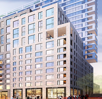

Figure 10: Tower A3/Podium Exterior Section
Figure 11 on the left shows the exterior construction of Tower A3. The brick veneer is shown in contrast to the concrete precast on tower A2 behind it.
Figure 11: Tower A3 Exterior Rendering
Roofing
As shown below, each tower’s roof is composed of multiple materials. The materials chosen are specific to that portion of the building’s intended use. For example, the mechanical yard utilizes a utility ballast roofing system, while an area meant to be more aesthetic such as the ninth-floor outdoor seating area has vegetated roof membranes.
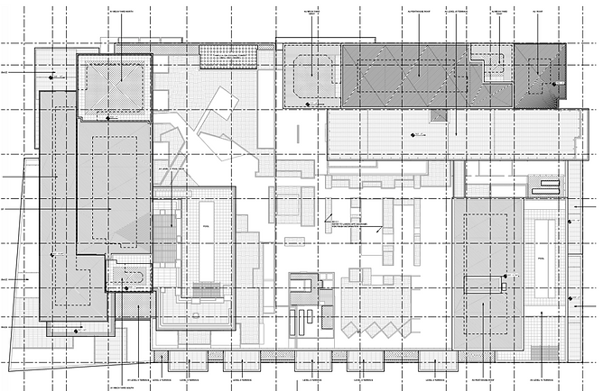
Figure 12: Building Roofing Systems

Figure 13: Building Roofing Systems Key
To provide further detail on a Mid Atlantic Mixed-Use Building roofing type, Figure 14 on the right provides a typical composition of a roof, specifically the decorative stone ballast roof. This roofing system is made up of the following (bottom to top):
-
Concrete slab
-
Asphalt primer
-
Hot Fluid-applied waterproofing
-
Protection Board
-
Drainage composite board
-
4” min rigid insulation
-
Filter fabric
-
Decorative stone ballast

Figure 14: Roof Composition
Sustainability Features
Sustainability
The Mid Atlantic Mixed-Use Building is on track to achieve LEED Gold certification through their building design, primarily focusing on recycled materials, and efficient mechanical systems. Specifically focusing on the mechanical design, the building utilizes two different systems, water source heat pumps for the A1, A2 and retail space areas, and a variable refrigerant system (VRF) for tower A3. The VRF system, which has a higher cost, was employed for Tower A3 because of its efficient performance when compared to other systems. However, the water source heat pumps on the project, although not as efficient as the VRF system, was vital in the buildings mission to achieve LEED Gold. The cooling towers that are part of the system use storm water that is collected in storm water cisterns located in the P1 Level of the garage. The size of the cisterns, and the water collected, makes it so that the cooling towers will only need to use water from these two areas and not rely on water coming from outside sources.
In addition to the mechanical systems, other sustainable building components include planters lining the exterior ground floors and vegetation roofs on Level 09.
Part 2
Construction
The Mid-Atlantic Mixed-Use Building’s structure is made entirely from cast-in-place concrete. To move and pour the concrete four tower cranes, concrete buckets and a concrete pump were used. The site of the Mid Atlantic Mixed-Use Building is sandwiched in between two roads and a neighboring construction site making site logistics very difficult.
The schedule of the Mid Atlantic Mixed-Use Building is unique in regards to sequencing. Since the building contains three towers, all of differing heights, a sequence had to be created where each tower's concrete structure could be finished around the same time. The structure was started in the north-west corner of the site (Tower A1) and then moved to the north-east (Tower A2) and then finally to the south of the site (Tower A3). Other than sequencing the main difficulty was meeting the schedule for the podium levels. Because of the podiums large size it was difficult to obtain the correct amount of labor and shifts that were required to complete the podium on time. Because of this, construction was delayed by two months, but once Level 09 was finished the construction team averaged a floor per week of each tower.
Structure


The Mid-Atlantic Mixed-Use Building’s structure is made entirely of cast-in-place concrete. To build the structure, the building was phased so that concrete placement was started in the north-west location, the A1 tower, before the rest of the site. Once the slab on grade was poured formwork was erected for the P1 deck. The formwork that was used was scaffolding topped with plywood. After concrete was allowed to cure the temporary scaffold bracing was removed and replaced with Doka posts, or post-shores, that would remain in place until the structure reached four floors above their location. This method served as the construction process for the entirety of the building.
The use of cast-in-place concrete posed a challenge in two areas: the organic grocery store vaulted ceiling and the loading dock space. The vaulted ceiling in the grocery store added extra time onto the construction schedule and required specially designed diagonal columns. The loading dock design required additional open floor space compared to the rest of the garage structure. To achieve this, two large post-tensioned transfer girders were added so that two column bays could be eliminated.
Figure 15: Transfer Girders
Figure 16: Transfer Girders
Envelope


There are two different building envelope systems used for the building. The first is a brick veneer system used on the podium and A3 tower levels. The brick veneer envelope is comprised of gypsum wall board, 6” insulation, 6” cfmf, 5/8” exterior sheathing, vapor permeable air and water barrier, 2” exterior insulation, laminated glass, and brick veneer. The second building exterior is a concrete precast system. The two precast systems are slightly different from one another. The first, used on tower A1, is made from ½” gypsum wall board, 3-5/8” stud to deck, air gap, 4” normal-rise spray foam with plastic stop angles, laminated glass, and one of three different precast colors (light gray, medium gray, or medium gray with custom texture). The second concrete precast system, used on tower A2, is constructed using ½” gypsum wall board, 3-5/8” stud to deck, 6” insulation, laminated glass, and one of two precast panel colors (white or medium gray). There are multiple roof types used on the project depending on the roofs intended usage. The majority of roofing is either a protected membrane roofing system or one of four different types of roof paver. What stands out about the roof design is the vegetative roof that is located on the ninth-floor terrace level and is part of the building’s sustainability initiative.
Figure 17: A1 Tower Enclosure

Figure 18: A2 Tower Enclosure
Figure 19: A3 Tower & Podium Enclosure
Mechanical
Two different mechanical systems are used in the building. The first system, used on tower A3, is a variable refrigerant flow system which is housed on the ninth-floor podium terrace and the level 13 A3 roof. The second system, water-source heat-pump serving towers A1, A2, and retail, is fed from three cooling towers in the A1 tower penthouse, two cooling towers located on the A2 tower penthouse, and an additional two cooling towers located in the eight-floor cooling tower well. All seven cooling towers are provided makeup water by two stormwater cisterns located in the P1 garage level. The primary mechanical rooms are located on the third, seventh, and eighth floor garage levels, as well as on the A1 and A2 penthouses.

Figure 20: Water-source Heat-pump
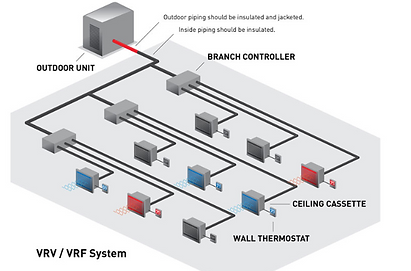
Figure 21: VRF System
Electrical & Lighting
The electrical system for all three towers stems from the P1 garage level where there are two transformer vaults that serve four main electric rooms adjacent to the vaults. In total there are ten transformers, six on the east and four on the west, that serve all three towers, podium and retail spaces. The electrical system is not unique in its design. Incoming Dominion Power Service is fed through the ten transformers, into electrical rooms containing switchgear. The power is then run to each respective location’s main panel boards, which in turn feed each living or retail space. Unique electrical features include the buildings use of one-hundred percent LED fixtures, occupancy sensors running throughout every garage level, and high-end chandeliers located in the A1 and A3 tower lobbies.

Figure 22: West Transformer Vault

Figure 22: East Transformer Vault
Transportation
The Mid Atlantic Mixed-Use Building has four different elevator lobbies: A1, A2, A3, and grocery store. Please see below for a breakdown of how many elevators belong to each lobby. In addition to elevators there are also 12 different stairways ranging from garage level P2 through each tower.
Total Number of Elevators
Tower A1 Lobby
Tower A2 Lobby
Tower A3 Lobby
Grocery Store Lobby
18
6
3
3
6
Fire Protection
The Mid Atlantic Mixed-Use Building uses two different types of sprinkler systems. In the garage levels (P2, P1, Level 04-09 garage) a dry pipe system is used, while the retail and residential areas use a wet pipe system.
Telecommunications
The Mid Atlantic Mixed-Use Building has three incoming telecommunication lines which come through the P2 Level of the garage. These lines then branch throughout the building through overhead conduit.
*All pictures are courtesy of the Mid Atlantic Mixed-Use Building website